Size an insulated shipping box around the assembled payload cavity and the closure, using the actual carton interior. Then make a physical sample. Nominal outside dimensions and a liner’s flat dimensions cannot show whether folds, overlaps and coolant leave enough usable space.
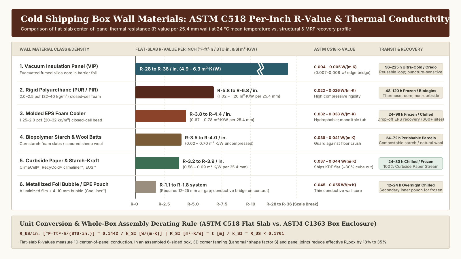
This worksheet is part of our protective packaging guides. It focuses on liner fit and assembly rather than choosing an inflatable packout system; for quantitative ASTM C518 thermal conductivity ratings, 3D corner conduction derating, and dry-ice or gel-pack sizing, pair this worksheet with our cold shipping boxes R-value and wall material comparison. When sizing flexible pouches rather than rigid cartons, use our insulated bubble mailers laminate and seal integrity guide to calculate 3D payload width clearance, preserve the internal radiant air gap, and qualify side-weld vs. PSA closures.
Measure the carton you will actually use
Erect a representative carton with its specified bottom closure. Record inside length, width and usable height using a consistent orientation. Note where the dimensions come from: an actual measurement, the carton drawing or a supplier’s nominal listing. Do not mix outside dimensions with an interior liner calculation.
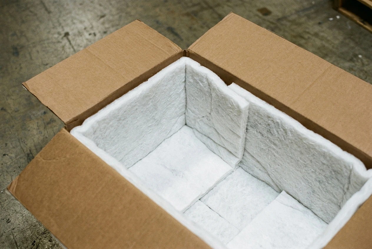
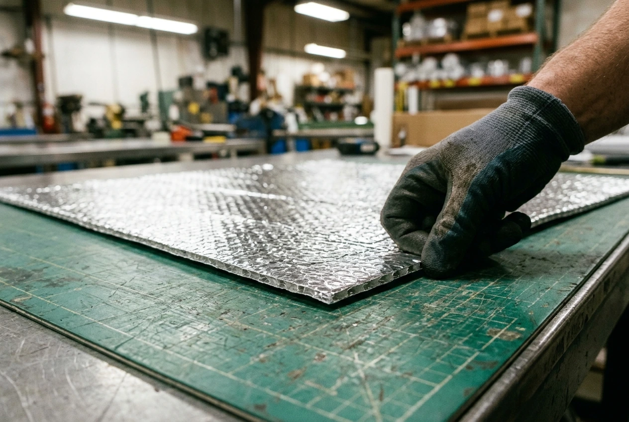
Inspect the corners as well as the broad faces. A flexible liner can take up extra room at a fold or overlap. A material’s uncompressed thickness on a flat sample may not describe the assembled corner.
Keep a dimension record with named reference surfaces
| Input | Reference to record | What it controls |
|---|---|---|
| Carton inside length and width | Erected carton and revision; measured faces | Maximum envelope available to the liner |
| Usable carton height | Bottom closure to permitted top closure plane | Room for payload, bottom material and top assembly |
| Liner build | Material identity, layer structure and thickness method | Initial allowance at each surface |
| Fold and seam geometry | Supplier drawing and overlap direction | Local buildup and assembly orientation |
| Payload envelope | Largest approved loaded arrangement | Required cavity, including projections |
| Other contents | Dividers, coolant or protection required by the selected packout | Space reserved outside the payload envelope |
| Closure allowance | Actual lid or flap instruction | Space that must remain free to close correctly |
Use a simple calculation only as a first screen
For a rigid rectangular liner with equal side thickness, an idealized cavity width is the carton inside width minus both side layers. Apply the same reasoning to length. Height needs separate bottom and top allowances. Flexible folds, seam buildup and tolerances require the sample check that follows.
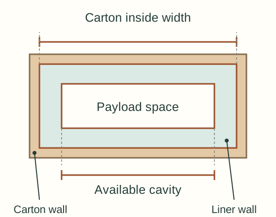
For illustration, suppose a carton measures 300 mm inside width and each opposing liner wall takes 20 mm. The nominal remaining width is 260 mm before any extra fold buildup, coolant or clearance—meaning a 260 mm wide payload leaves zero assembly clearance before accounting for corner fold buildup or gel packs.
Do not calculate a cut blank by adding those cavity dimensions alone. A finished liner drawing must specify seams, gussets, overlaps and closure geometry. The converting handoff guide explains which checks belong to that stage.
Assemble the load before approving the fit
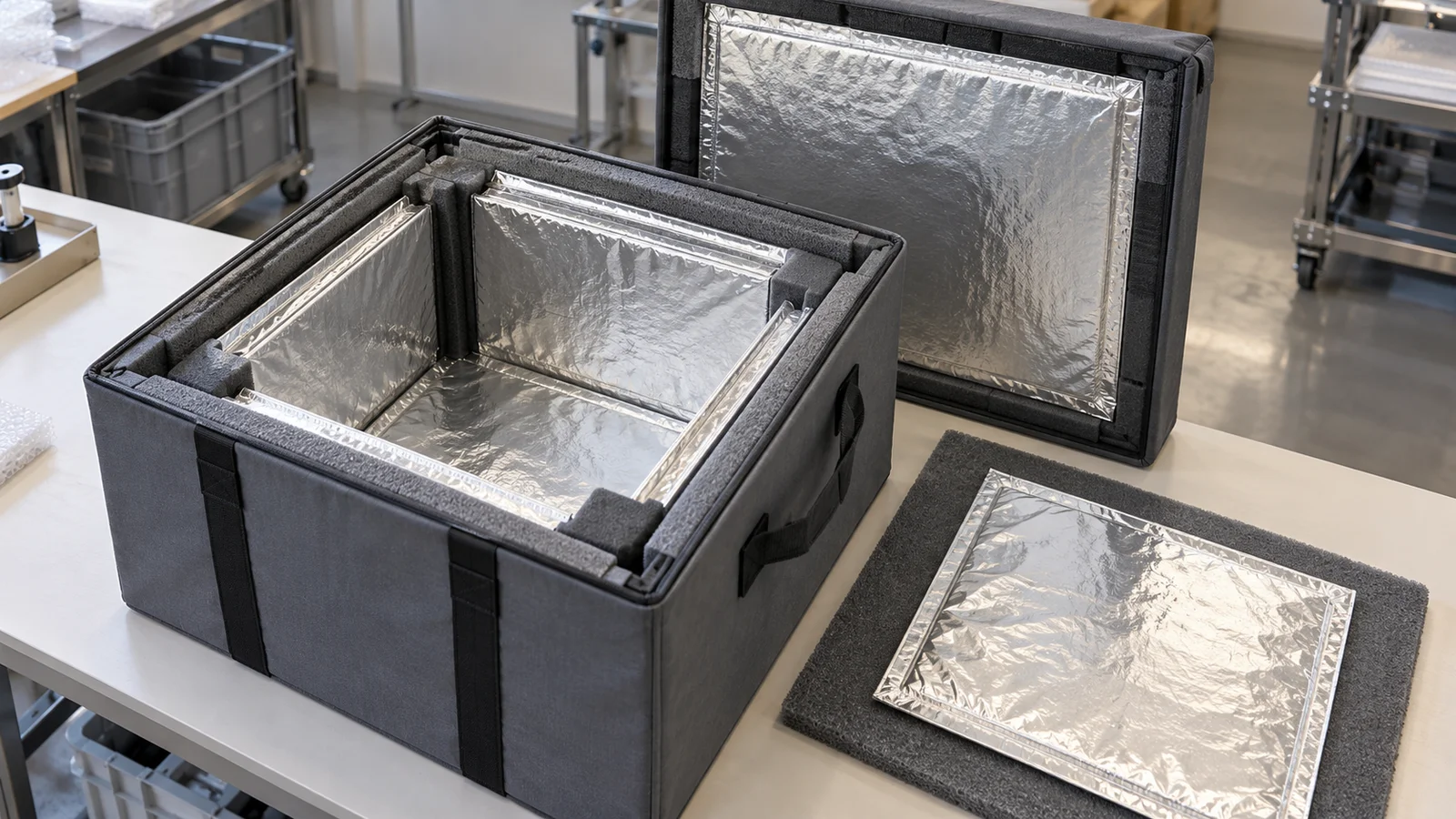
Install the liner according to its drawing. Check bottom coverage and the direction of each corner fold. Insert a representative payload with every required accompanying component, then bring the inner closure into its working position. Photograph the result before closing the carton.
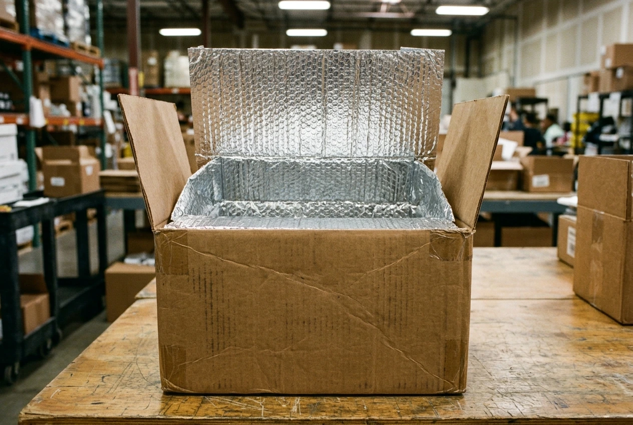
Inspect for pulled corners, exposed gaps, a flap trapped by the load and a top closure that must be forced down. If the carton bulges, record where the interference occurs. Avoid trimming the liner or compressing insulation to make a nominal cavity calculation appear correct.
Repeat the check with the approved load extremes and representative material variation. Record the configuration actually used. The result can confirm that a sample assembles; it does not establish thermal suitability for a new load or route.
Release a drawing and sample together
A useful handoff contains the carton reference, liner drawing, material identity, measured cavity, closure arrangement and approved sample photographs. State which dimension is critical at each inspection point. Keep deviations visible so a purchasing substitution does not quietly become a new packaging design.
Method and sources
IPC’s liner documentation establishes that custom sizing, collapsible construction and closure options are product-specific. Validate physical clearance and thermal duration on assembled samples under your target transit profile.