Selecting cold shipping boxes from a flat-sheet thermal resistance datasheet alone causes premature refrigerant depletion, payload temperature excursions, and rejected frozen shipments when three-dimensional corner conduction and panel seam gaps increase heat ingress by 18% to 35%. Sizing insulated boxes for shipping frozen food (≤ -18 °C / 0 °F) or chilled perishables (+2 °C to +8 °C / 36 °F to 46 °F) requires pairing the material’s ASTM C518 thermal conductivity rating with the assembled enclosure’s 3D shape factor, corner joint architecture, and phase-change refrigerant mass.
Within our protective mailers and boxes series, the insulated shipping boxes liner dimension worksheet establishes how wall thickness and corner folds deduct from the usable interior carton cavity (for example, a 300 mm inside carton width minus two 20 mm liner walls leaves a 260 mm nominal cavity before fold buildup). This companion engineering guide supplies the quantitative thermal counterpart: comparing steady-state k-values and per-inch thermal shipping box r value ratings across six commercial wall materials, deriving the assembled-box conduction derating equations, and sizing wall thickness (1.0 in., 1.5 in., 2.0 in.) alongside dry ice or 0 °C gel pack mass for 24 h, 48 h, and 72 h parcel lanes.
Compare thermal conductivity and per-inch R-value across six cold shipping box materials
When evaluating supplier datasheets for cold shipping boxes or comparing insulated protective packaging constructions, packaging engineers must reconcile two measurement unit systems and test boundaries documented by the National Insulation Association and Metal Architecture:
- Steady-State Thermal Conductivity (
k-Value orλ,ASTM C518/ASTM C177): Measured on a flat, uncompressed material specimen clamped between two temperature-controlled plates in a steady-state heat flow meter apparatus (ASTM C518) or guarded hot plate (ASTM C177), typically reported at a24 °C(75 °F) or10 °C(50 °F) mean test temperature. Thermal conductivitykexpresses the heat flux (W/m²) conducted through a1 mthickness per1 K(1 °C) temperature difference:- SI Conductivity Units:
W/(m·K) - US Customary (IP) Conductivity Units:
BTU·in./(h·ft²·°F), where1 BTU·in./(h·ft²·°F) = 0.144228 W/(m·K)
- SI Conductivity Units:
- Material Thermal Resistance (
R-Value) and Conductance (U-Factor): For a flat insulation layer of uniform thicknesst, thermal resistance is the ratio of thickness to conductivity (R = t / k), and unit conductance is its reciprocal (U = 1 / R):
R_US/in. [°F·ft²·h / (BTU·in.)] = 1 / k_IP = 0.144228 / k_SI [W/(m·K)]

R_SI [m²·K / W] = t [m] / k_SI [W/(m·K)] = R_US × 0.17611
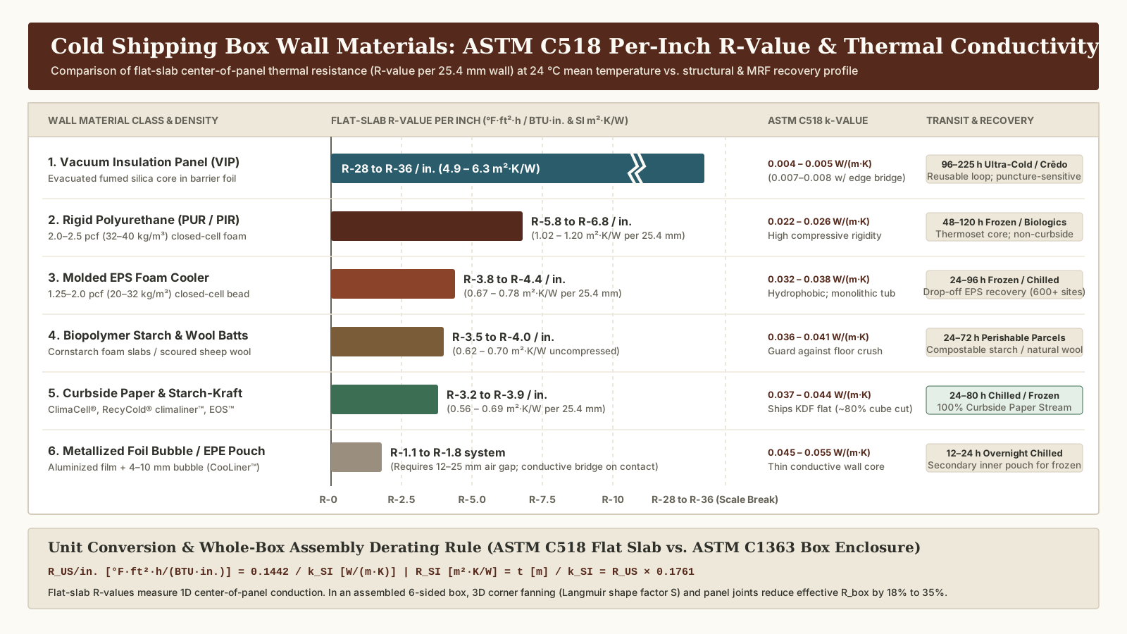
For example, a molded Expanded Polystyrene (EPS) cooler wall with k_SI = 0.035 W/(m·K) provides a center-of-wall thermal resistance of R_US/in. = 0.144228 ÷ 0.035 = 4.12 °F·ft²·h/(BTU·in.), which equals R_SI = 0.0254 m ÷ 0.035 W/(m·K) = 0.726 m²·K/W per inch (25.4 mm) of wall thickness.
| Wall Material Class & Commercial Examples | ASTM C518 Conductivity k at 24 °C (W/(m·K)) |
Flat-Slab R-Value per Inch (°F·ft²·h/BTU·in. & SI) |
Structural Load & Condensation Behavior | Typical Transit Window & End-of-Life MRF Pathway |
|---|---|---|---|---|
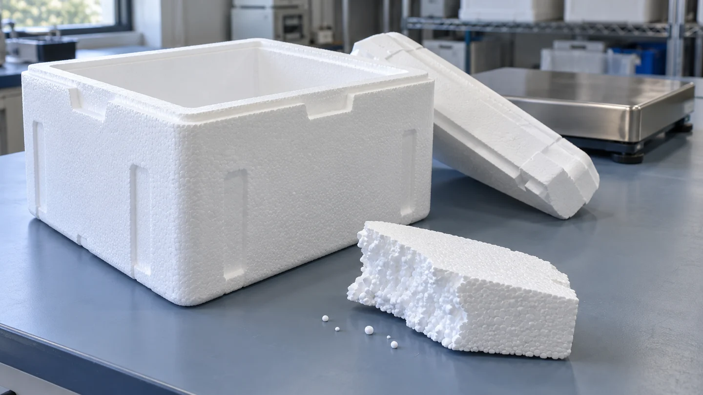
1. Expanded Polystyrene (EPS Molded Cooler)1.25–2.0 pcf (20–32 kg/m³) closed-cell bead foam (Sonoco ThermoSafe® Envoy / Certis, Peli BioThermal™ Sherpa™ DeepFreeze) |
0.032 – 0.038 W/(m·K) |
R-3.8 to R-4.4 / in.( 0.67 – 0.78 m²·K/W per 25.4 mm) |
Self-supporting rigid molded tub with stepped tongue-and-groove lid; hydrophobic closed cells resist payload crushing and gel-pack sweat | 24 h – 96 h frozen / chilled; high inbound warehouse storage cube; EPS drop-off recovery (600+ North American sites) |
2. Rigid Polyurethane / Polyisocyanurate (PUR / PIR)2.0–2.5 pcf (32–40 kg/m³) closed-cell foam (ThermoSafe® PUR shippers) |
0.022 – 0.026 W/(m·K) |
R-5.8 to R-6.8 / in.( 1.02 – 1.20 m²·K/W per 25.4 mm) |
High compressive modulus and 45%–55% higher R/in. than EPS; produced as foamed-in-place chests or 6-panel mitered/butt-jointed KDF kits |
48 h – 120 h+ frozen / specialty biologics; thermoset core is not curbside recyclable |
3. Vacuum Insulation Panels (VIP, Fumed Silica Core)Evacuated microporous silica in metallized barrier film (Peli BioThermal™ Crēdo™ Cube, ThermoSafe® VIP) |
0.004 – 0.005 W/(m·K)( 0.007–0.008 effective with edge foil bridge) |
R-28 to R-36 / in.( 4.9 – 6.3 m²·K/W per 25.4 mm; 7×–8× EPS) |
Fragile evacuated barrier foil requires protective EPP/EPS/PE foam casing; film puncture degrades core to R-7/in. ambient silica |
96 h – 225 h ultra-cold (-65 °C to -20 °C) or +2 to +8 °C; minimizes dry ice mass and parcel DIM weight in reusable loops |
| 4. Curbside-Recyclable Paper & Starch-Kraft Liners Fluted kraft plies or bio-starch foam + kraft (TemperPack ClimaCell®, Ranpak RecyCold® climaliner™, ThermoSafe EOS™) |
0.037 – 0.044 W/(m·K) |
R-3.2 to R-3.9 / in.( 0.56 – 0.69 m²·K/W per 25.4 mm) |
Ships knock-down-flat (KDF) as pre-hinged panels (ClimaCell) or multi-ply waved kraft (RecyCold); requires moisture-resistant kraft facing against condensate |
24 h – 80 h chilled / frozen (double or triple wall for >48 h); 100% curbside recyclable in residential paper streams (How2Recycle®) |
| 5. Biopolymer Cornstarch & Natural/Recycled Fiber Batts Extruded starch slabs (Green Cell Foam®), scoured sheep wool (Woolcool®), or non-woven PET/cotton mats |
0.036 – 0.041 W/(m·K)(uncompressed dry batt or slab) |
R-3.5 to R-4.0 / in.( 0.62 – 0.70 m²·K/W uncompressed) |
Starch panels form semi-rigid water-soluble slabs; flexible fibrous mats rely on outer carton and compress under heavy payloads or dry ice blocks | 24 h – 72 h perishable food; starch composts/dissolves, wool is reusable/compostable, while non-woven PET mats fail MRF bottle sorting |
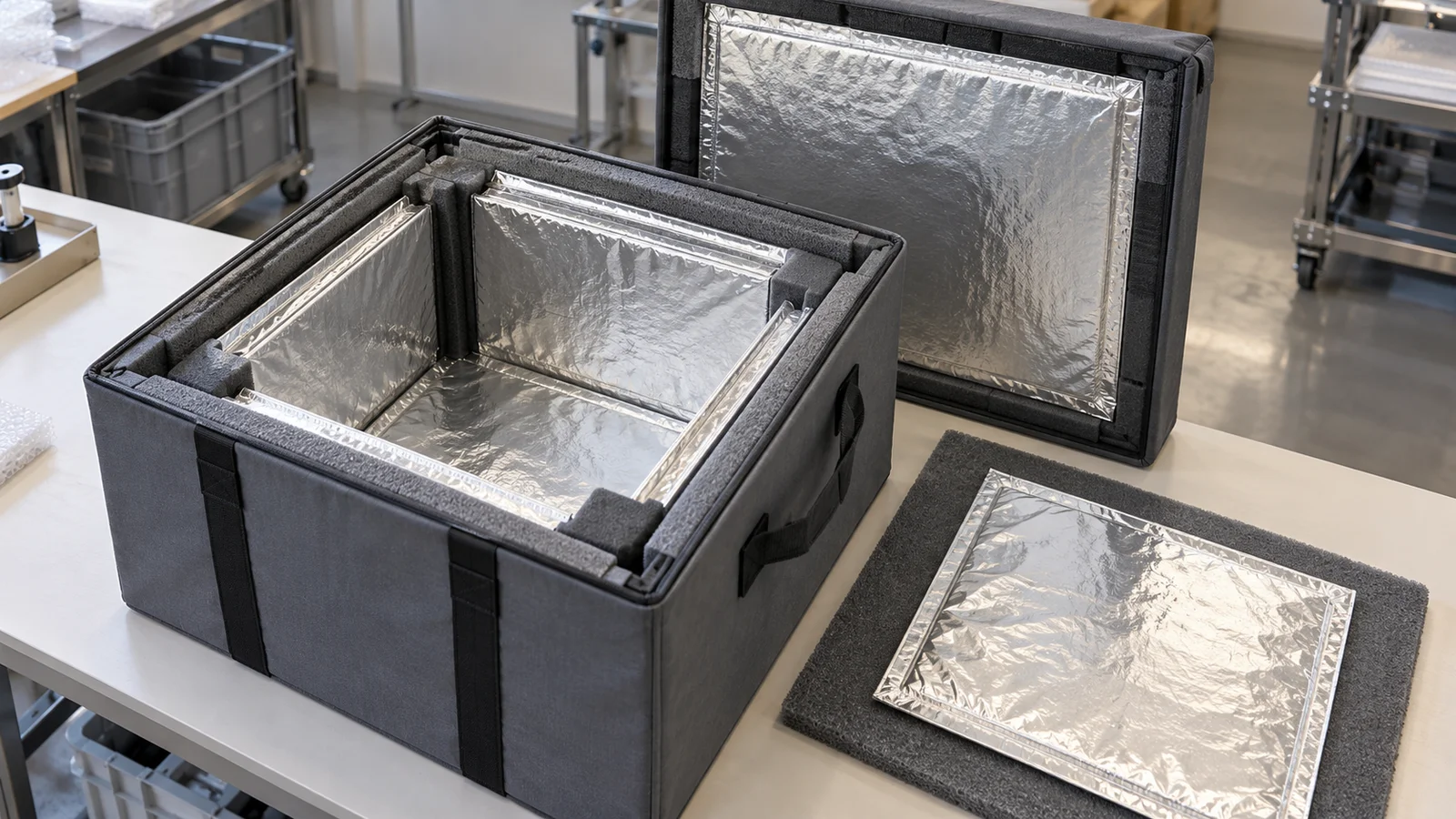
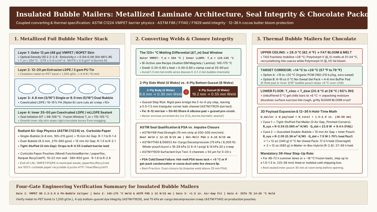
| 6. Metallized Foil Bubble & EPE Foam Liners Aluminized PET/LDPE film + 4–10 mm bubble/EPE core (IPC CooLiner™ collapsible liner) |
0.045 – 0.055 W/(m·K)(conductive wall core) |
R-1.1 to R-1.8 system(requires 12–25 mm dead air gap) |
Low-emissivity foil blocks radiant heat across an open air space, but direct payload or coolant contact against thin 6–8 mm walls bridges conduction |
12 h – 24 h overnight chilled (or secondary inner pouch inside a rigid box); insufficient standalone conductive R for 48–72 h frozen dry ice |
Structural compression and MRF recyclability differences between fibrous liners and rigid foams
Material conductivity tells only half the story during transit and end-of-life disposition. In Sonoco ThermoSafe’s engineering comparison of non-woven PET liners versus molded EPS and cellulose shippers, three mechanical and regulatory failure modes separate flexible fibrous batts from rigid closed-cell or semi-rigid paper-based structures:
- Bottom-Wall Compression Under Payload and Coolant Load (
tReduction): Because thermal resistance scales linearly with wall thickness (R = t / k), a flexible non-woven PET or shoddy-cotton batt that compresses from38 mm(1.5 in.) down to19 mm(0.75 in.) under a10 kgfrozen meat payload and dry ice slab loses nearly50%of its floor thermal resistance. By contrast, closed-cell molded EPS (1.25–2.0 pcf), rigid PUR (2.0–2.5 pcf, documented by Construction Specifier atR-6.0/in.), and semi-rigid starch-kraft panels (TemperPack ClimaCell®) maintain constant wall thickness across the bottom bearing surface. - Condensation Wicking vs. Vapor Barrier Encapsulation:
When water-based
0 °Cgel packs sweat during humid summer unloading, exposed hydrophilic fibers wick liquid water (k_water ≈ 0.60 W/(m·K)—roughly15×more conductive than still air), collapsing the insulation value. Systems such as Woolcool® enclose scoured sheep’s wool inside a micro-perforated polyethylene film envelope, while Ranpak RecyCold® climaliner™ and TemperPack ClimaCell® use moisture-resistant kraft outer plies to protect the air-trapping core. - Municipal MRF Sorting Physics (
SB 343andFTC Green GuidesCompliance): Although flexible non-woven PET liners carry resin identification code#1, municipal Materials Recovery Facilities (MRFs) tune optical sorters and ballistic separators for rigid three-dimensional PET bottles. Flexible PET fiber batts flatten on belt conveyors and wrap around rotating star screens, failing the60%community access threshold under the FTC Green Guides and CaliforniaSB 343. Shippers requiring verified curbside recovery must select repulpable paper-stream architectures such as Sonoco ThermoSafe EOS™ (100%paper fiber), TemperPack ClimaCell®, or Ranpak RecyCold® climaliner™.
Key Takeaway: Always pair an
ASTM C518per-inchR-value with the material’s loaded bottom thickness under full payload plus coolant weight. Rigid PUR (R-5.8 to R-6.8/in.) and VIPs (R-28 to R-36/in.) maximize thermal hold in compact outer cartons, whereas molded EPS (R-3.8 to R-4.4/in.) and curbside-recyclable paper/starch-kraft liners (R-3.2 to R-3.9/in.) anchor24–72 hfood and parcel distribution.
Why assembled box R-value drops 18% to 35% below flat-slab datasheet ratings
As documented by Metal Architecture and the National Insulation Association alongside Sonoco ThermoSafe ISC Labs’ ISTA thermal modeling guidance, a material supplier’s ASTM C518 rating (R_slab = t / k) measures one-dimensional heat flow through the center of an infinite, jointless slab. Once six panels or a die-cut folding blank are installed inside a corrugated carton (see our insulated liner converting traveler), the effective whole-box thermal resistance (R_box) drops by 18% to 35% and must be evaluated at the whole-enclosure level (ASTM C1363 hot-box assembly testing or calibrated 3D chamber qualification).
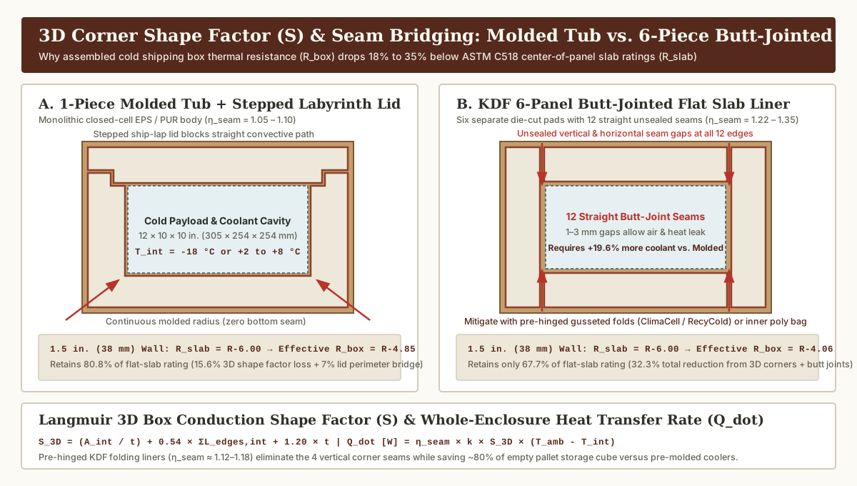
Two distinct physical mechanisms cause this whole-box derating:
1. Three-dimensional corner and edge conduction (Langmuir’s 3D shape factor S_3D)
In a thick-walled rectangular cold shipping box (where wall thickness t = 25 to 51 mm represents a substantial fraction of the internal cavity dimensions), the exterior carton surface area absorbing ambient heat (A_ext) is 40% to 85% larger than the interior cold cavity surface area (A_int). Heat flux lines fan outward through all 12 internal box edges and 8 box corners.
For a rectangular enclosure with interior cavity dimensions L_int × W_int × H_int and uniform insulation thickness t > 0.2 × min(L_int, W_int, H_int) (all in meters), total 3D geometric conduction is governed by Langmuir’s 3D box conduction shape factor (S_3D):
A_int = 2 × (L_int × W_int + L_int × H_int + W_int × H_int)        [m²]
ΣL_edges,int = 4 × (L_int + W_int + H_int)                         [m]

S_3D = (A_int / t) + (0.54 × ΣL_edges,int) + (1.20 × t)            [m]
Where:
A_int / trepresents one-dimensional planar conduction through the 6 flat interior faces,0.54 × ΣL_edges,intaccounts for two-dimensional heat fanning across the 12 internal edges, and1.20 × taccounts for three-dimensional conduction through the 8 corners.
Packaging engineers also approximate this geometric divergence using the geometric mean surface area (A_mean) between the outer insulation boundary (A_ext) and the inner cavity boundary (A_int):
A_mean = sqrt(A_ext × A_int) [m²]2. Panel joint and corner seam thermal bridging multiplier (η_seam)
Even after accounting for 3D geometry (S_3D), an assembled cold box only matches the theoretical conduction rate (Q_dot,ideal = k × S_3D × ΔT) if the insulation shell is monolithic and airtight. In production packouts, panel seams, fold creases, and lid gaps introduce a seam bridging multiplier (η_seam = 1.05 to 1.40):
(UA)_box [W/K] = η_seam × k_SI × S_3D

Q_dot,actual [W] = (UA)_box × (T_amb - T_int)

R_box,eff (referenced to A_int) = R_slab / [ (t × S_3D / A_int) × η_seam ]| Enclosure Joint Architecture | Corner & Edge Seam Geometry | Seam Bridging Multiplier (η_seam) |
Effective R_box Retained vs. R_slab |
Inbound Freight Cube & Packing Station Tradeoff |
|---|---|---|---|---|
| 1. One-Piece Molded Tub + Stepped Labyrinth Lid (Molded EPS / EPP or Foamed-in-Place PUR) |
Zero vertical wall or floor seams; top lid engages a stepped ship-lap / tongue-and-groove perimeter seal | 1.05 – 1.10( 5%–10% lid-seam loss) |
78% – 82% of R_slab |
Highest thermal integrity for 48–96 h frozen dry ice shipments; consumes 4×–7× more inbound trailer and pallet storage volume than flat liners |
| 2. KDF Pre-Hinged / Gusseted 2-Piece Folding Liners (TemperPack ClimaCell®, Ranpak RecyCold® climaliner™) |
Pre-formed living hinges or continuous multi-ply wrap eliminate 4 vertical corner seams; top and bottom flaps seat against inner faces | 1.12 – 1.18( 12%–18% fold/flap bridge) |
70% – 76% of R_slab |
Ships and stores flat on pallets (cuts warehouse cube by ~80%); fast 2-piece erection (verify corner seating per liner fit guide) |
| 3. KDF 6-Piece Butt-Jointed Flat Slab Kits (Die-cut EPS, PUR, or Cornstarch 6-pad kits) |
12 unsealed straight butt joints (4 vertical corners + 4 top + 4 bottom edges); 1–3 mm dimensional tolerances create convective air paths |
1.22 – 1.35( 22%–35% butt-joint leak) |
65% – 72% of R_slab |
Zero mold tooling cost and flat pallet storage, but slower 6-pad hand assembly and high sensitivity to outer carton bulging |
| 4. Flexible Fibrous Batt or Collapsible Reflective Pouch (Non-woven PET/cotton pads, Woolcool®, IPC CooLiner™) |
Flexible blanket or pouch conforms to carton, but corner folds pinch thin and heavy payloads compress the bottom pad | 1.25 – 1.40(compression + fold thinning) |
60% – 70% of uncompressed R_slab |
Requires checking incoming web thickness (see slitting & rewinding guide) and sealing the inner bag mouth (see bag sealer guide) |
Worked 3D shape-factor and seam derating calculation (12 × 10 × 10 in. cavity with 1.5 in. walls)
Consider a frozen food parcel box with an interior payload cavity of 12 × 10 × 10 in. (L_int = 0.3048 m, W_int = 0.2540 m, H_int = 0.2540 m, usable volume = 19.66 L) insulated with t = 1.5 in. (0.0381 m) walls (k = 0.036 W/(m·K), datasheet R_slab = R-4.00/in. × 1.5 in. = R-6.00 or 1.058 m²·K/W) inside a 15 × 13 × 13 in. (0.3810 × 0.3302 × 0.3302 m) outer corrugated box:
- Interior, Exterior, and Geometric Mean Areas:
A_int = 2 × (0.3048 × 0.2540 + 0.3048 × 0.2540 + 0.2540 × 0.2540) = 0.4387 m²(4.722 ft²)A_ext = 2 × (0.3810 × 0.3302 + 0.3810 × 0.3302 + 0.3302 × 0.3302) = 0.7213 m²(7.764 ft²)A_mean = sqrt(0.7213 × 0.4387) = 0.5625 m²(6.055 ft²—28.2%larger thanA_int)
- Langmuir 3D Box Conduction Shape Factor (
S_3D):- Sum of 12 interior edges:
ΣL_edges,int = 4 × (0.3048 + 0.2540 + 0.2540) = 3.2512 m S_3D = (0.4387 ÷ 0.0381) + (0.54 × 3.2512) + (1.20 × 0.0381) = 11.514 + 1.756 + 0.046 = 13.316 m- One-dimensional interior-area conduction (
A_int / t = 11.514 m) underpredicts 3D geometric conduction (S_3D = 13.316 m) by15.6%from edge and corner fanning alone.
- Sum of 12 interior edges:
- Effective Whole-Box Conductance (
UA) and DeratedR_box:- Architecture A — 1-Piece Molded EPS Chest (
η_seam = 1.07):(UA)_molded = 1.07 × 0.036 W/(m·K) × 13.316 m = 0.5129 W/K. Referenced to the interior payload boundary (A_int), effective thermal resistance isR_box,eff = R-6.00 ÷ (1.1565 × 1.07) = R-4.85(a19.2%reduction below theR-6.00flat-slab rating). - Architecture B — KDF Pre-Hinged 2-Piece Liner (
η_seam = 1.15):(UA)_hinged = 1.15 × 0.036 W/(m·K) × 13.316 m = 0.5513 W/K, yieldingR_box,eff = R-4.51(a24.8%reduction belowR_slab). - Architecture C — KDF 6-Panel Butt-Jointed Slab Liner (
η_seam = 1.28):(UA)_6-panel = 1.28 × 0.036 W/(m·K) × 13.316 m = 0.6136 W/K, dropping effective resistance toR_box,eff = R-4.06(a32.3%reduction belowR_slab, requiring19.6%more dry ice or gel pack mass than the 1-piece molded cooler of the exact same1.5 in.thickness).
- Architecture A — 1-Piece Molded EPS Chest (
Key Takeaway: Never plug an
ASTM C518center-of-panelR_slabdirectly into a1Dinterior-area heat transfer formula (Q = A_int × ΔT / R_slab). Applying Langmuir’s 3D shape factor (S_3D) and the joint bridging multiplier (η_seam) prevents undersizing refrigerant mass by20% to 35%.
Size wall thickness and refrigerant mass for 24-hour, 48-hour, and 72-hour frozen and chilled shipments
In insulated boxes for shipping frozen food (≤ -18 °C / 0 °F meats, seafood, ice cream, and frozen meal kits) or refrigerated pharmaceuticals and perishables (+2 °C to +8 °C), the insulation wall thickness (t) and the phase-change coolant mass (M_coolant) form a coupled heat-balance system.
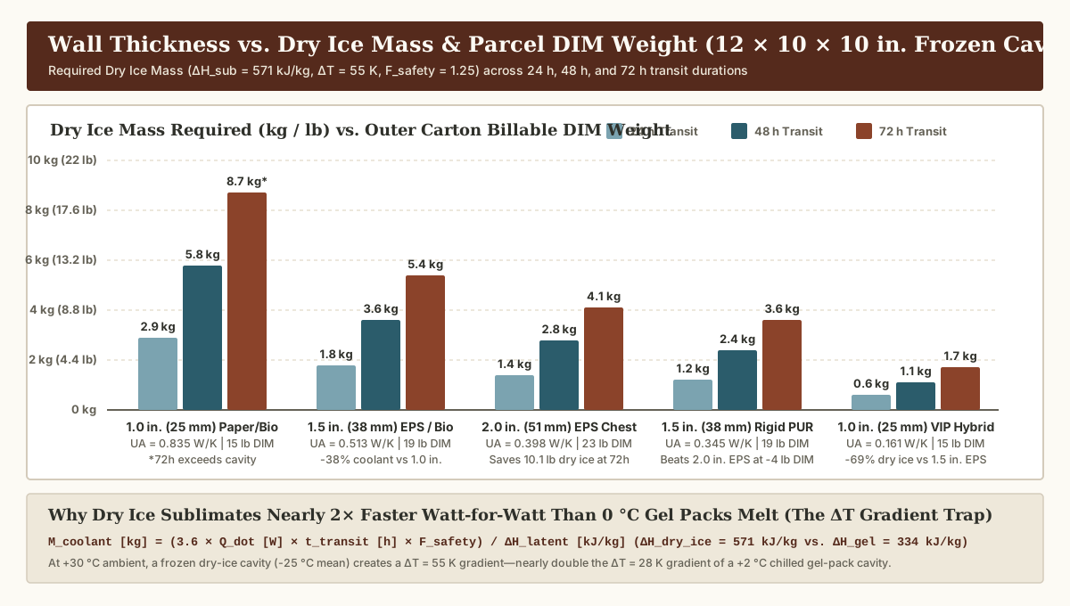
Steady-state heat ingress (Q_total) and phase-change coolant mass (M_coolant)
During a transit duration t_transit (in hours) across an external ambient temperature T_amb and target internal cavity temperature T_int (where ΔT = T_amb - T_int in K or °C), the steady-state heat transfer rate (Q_dot in Watts), cumulative transit heat load (Q_total in kilojoules), and required refrigerant mass (M_coolant in kilograms) follow:
Q_dot [W] = (UA)_box × ΔT = η_seam × k_SI × S_3D × (T_amb - T_int)

Q_total [kJ] = (Q_dot [W] × t_transit [h] × 3,600 [s/h]) / 1,000 = 3.6 × Q_dot × t_transit

M_coolant [kg] = (Q_total [kJ] × F_safety) / ΔH_latent [kJ/kg]
Where:
F_safety = 1.20 to 1.30is the engineering safety margin (20% to 30%buffer) accounting for initial warm box wall pull-down, hub sortation exposure, and final-mile porch dwell, andΔH_latentis the phase-change latent heat of fusion or sublimation (kJ/kg) of the selected refrigerant. This equation requires that the product payload is pre-frozen or pre-chilled to its target storage temperature before packing so the coolant absorbs external heat ingress (Q_total) rather than pulling down warm product mass.
Water-based 0 °C gel packs vs. -78.5 °C dry ice: the ΔT thermal gradient trap
Comparing the two primary cold-chain parcel refrigerants documented by Sonoco ThermoSafe and Peli BioThermal reveals a critical thermodynamic counter-intuition:
- Water-Based
0 °C(+32 °F) Gel Packs / PCM Bricks (Chilled+2 °C to +8 °CShipments):- Latent Heat of Fusion (
ΔH_fusion):334 kJ/kg(143.6 BTU/lb) at0 °C. - Thermal Driving Potential (
ΔT_chilled): Against a+30 °C(86 °F) summer mean ambient (ISTA 7E / 7Dstress baseline) and a+2 °Cinternal cavity boundary, the temperature gradient across the box wall isΔT_chilled = 30 - 2 = 28 K(50.4 °F).
- Latent Heat of Fusion (
- Solid Carbon Dioxide — Dry Ice Blocks / Pellets (Frozen
≤ -18 °CShipments):- Latent Heat of Sublimation (
ΔH_sub):571 kJ/kg(245.5 BTU/lb) at-78.5 °C(-109.3 °F) (plus ~60 kJ/kg of sensible gas warming as cold CO₂ vapor warms toward -20 °C before venting). - Why Dry Ice Sublimates Nearly
2×Faster Watt-for-Watt (ΔT_frozen = 55 K): Even though dry ice absorbs1.71×more heat per kilogram than melting water gel (571vs.334 kJ/kg), dry ice chills the internal enclosure air toward-25 °C to -35 °C. Against a+30 °Csummer ambient,ΔT_frozen = 30 - (-25) = 55 K(99 °F)—nearly double the28 Kdriving force of a chilled box! Because conductive heat ingress (Q_dot) is directly proportional toΔT, heat rushes into a frozen dry-ice box1.96×faster than into an identical box holding+2 °Cchilled product, causing dry ice to sublimate at3% to 10%+of total block mass per day depending on wallR-value.
- Latent Heat of Sublimation (
Wall thickness (1.0 in., 1.5 in., 2.0 in.) and coolant mass sizing matrix (12 × 10 × 10 in. cavity)
The engineering planning matrix below models a standardized 12 × 10 × 10 in. (305 × 254 × 254 mm, 19.7 L) internal cavity at +30 °C mean external ambient with F_safety = 1.25, comparing chilled gel pack mass (ΔT = 28 K, ΔH = 334 kJ/kg), frozen dry ice mass (ΔT = 55 K, ΔH = 571 kJ/kg), and parcel carrier dimensional weight (DIM weight = L_ext × W_ext × H_ext ÷ 139 in³/lb):
| Wall Thickness & Insulation Construction | Outer Carton Size & Carrier DIM Weight (÷ 139) |
Whole-Box Conductance (UA)_box (W/K) |
Chilled (+2 to +8 °C) 0 °C Gel Pack Mass (24h / 48h / 72h) |
Frozen (≤ -18 °C) Dry Ice Block Mass (24h / 48h / 72h) |
Optimal Parcel Lane & Engineering Tradeoff |
|---|---|---|---|---|---|
1.0 in. (25.4 mm) KDF Paper / Starch Liner(ClimaCell® / RecyCold®, k = 0.039 W/(m·K), R_slab = 3.7, η_seam = 1.15) |
14 × 12 × 12 in.( 2,016 in³ → 15 lb DIM) |
0.835 W/K( R_box,eff = R-2.99) |
• 24 h: 2.5 kg (5.5 lb)• 48 h: 5.0 kg (11.1 lb)• 72 h: 7.5 kg (16.6 lb*) |
• 24 h: 2.9 kg (6.4 lb)• 48 h: 5.8 kg (12.8 lb)• 72 h: 8.7 kg (19.2 lb*) |
24 h – 36 h overnight / regional 2-day chilled meal kits or short-haul frozen parcels; *at 72 h, coolant volume crowds out payload cavity |
1.5 in. (38.1 mm) Molded EPS or Hinged Bio-Liner( k = 0.036 W/(m·K), R_slab = 6.0, η_seam = 1.07–1.15) |
15 × 13 × 13 in.( 2,535 in³ → 19 lb DIM) |
0.513 – 0.551 W/K( R_box,eff = R-4.85) |
• 24 h: 1.6 kg (3.5 lb)• 48 h: 3.2 kg (7.0 lb)• 72 h: 4.8 kg (10.5 lb) |
• 24 h: 1.8 kg (4.0 lb)• 48 h: 3.6 kg (8.0 lb)• 72 h: 5.4 kg (11.9 lb) |
Workhorse 48 h frozen food & chilled parcel standard; cuts dry ice and gel mass by 34%–38% vs. 1.0 in. wall (saving 4.8 lb of dry ice at 48 h) |
2.0 in. (50.8 mm) Molded EPS Chest( k = 0.035 W/(m·K), R_slab = 8.2, η_seam = 1.07) |
16 × 14 × 14 in.( 3,136 in³ → 23 lb DIM) |
0.398 W/K( R_box,eff = R-6.25) |
• 24 h: 1.2 kg (2.6 lb)• 48 h: 2.4 kg (5.3 lb)• 72 h: 3.6 kg (7.9 lb) |
• 24 h: 1.4 kg (3.1 lb)• 48 h: 2.8 kg (6.1 lb)• 72 h: 4.1 kg (9.1 lb) |
48 h – 72 h+ national summer frozen shipping; cuts 72 h dry ice load from 19.2 lb (1.0 in.) down to 9.1 lb, offsetting the +4 lb DIM step |
1.5 in. (38.1 mm) Rigid Polyurethane (PUR) Shipper( k = 0.024 W/(m·K), R_slab = 9.0, η_seam = 1.08) |
15 × 13 × 13 in.( 2,535 in³ → 19 lb DIM) |
0.345 W/K( R_box,eff = R-7.21) |
• 24 h: 1.0 kg (2.3 lb)• 48 h: 2.1 kg (4.6 lb)• 72 h: 3.1 kg (6.9 lb) |
• 24 h: 1.2 kg (2.6 lb)• 48 h: 2.4 kg (5.3 lb)• 72 h: 3.6 kg (7.9 lb) |
72 h – 96 h frozen / specialty pharma; outperforms 2.0 in. EPS in a 1.5 in. wall, saving 4 lb of parcel DIM weight per box |
1.0 in. (25.4 mm) Vacuum Insulated Panel (VIP) Hybrid( k_eff = 0.0075 W/(m·K), R_slab ≈ 28, η_seam = 1.15, Crēdo™ / Orion™) |
14 × 12 × 12 in.( 2,016 in³ → 15 lb DIM) |
0.161 W/K( R_box,eff = R-15.4) |
• 24 h: 0.5 kg (1.1 lb)• 48 h: 1.0 kg (2.1 lb)• 72 h: 1.5 kg (3.2 lb) |
• 24 h: 0.6 kg (1.2 lb)• 48 h: 1.1 kg (2.5 lb)• 72 h: 1.7 kg (3.7 lb) |
96 h – 225 h international air & biologics; cuts 72 h dry ice mass by 69% vs. 1.5 in. EPS inside the smallest 14 × 12 × 12 in. outer cube |
Key Takeaway: Engineering rule of thumb for frozen food parcels: if a
48 hor72 hshipment requires refrigerant mass exceeding35%of the internal cavity volume (or > 5 kg of dry ice in a 20 L cavity), increase wall thickness from1.0 in.to1.5 in.or2.0 in.rather than stuffing extra dry ice into a thin-walled box.
Run a four-gate packout verification before qualifying the shipping lane
Once wall thickness and coolant mass are selected, packaging engineers must connect physical carton-and-liner fit checks (see liner dimensions and assembly inputs and liner converting) with thermal chamber qualification (ISTA 7D or ISTA 7E). As Sonoco ThermoSafe’s ISC Labs documentation notes, ISTA 7E represents a continuous 20-year industry-standard ambient profile derived from an 82-lane North American temperature study, whereas ISTA 7D applies step-function temperature extremes with steeper peaks and troughs alongside World Health Organization (WHO TRS 961 Annex 9) Design Qualification (DQ), triplicate chamber Operational Qualification (OQ), and field Lane Performance Qualification (PQ).
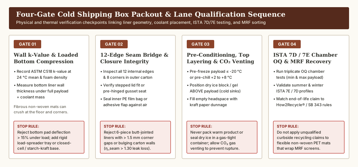
Use this four-gate verification sequence to prevent thermal bridging, premature sublimation, and MRF labeling violations before releasing a cold shipping box to production:
| Verification Gate | Engineering Parameter to Record | Acceptance Threshold & Mandatory Stop Rule |
|---|---|---|
Gate 1: Wall k-Value, Density & Loaded Bottom Compression |
Record ASTM C518 conductivity k (W/(m·K) at 24 °C mean), foam density (1.25–2.0 pcf EPS vs. 2.0–2.5 pcf PUR) or paper/fiber basis weight, and loaded bottom-pad thickness under maximum payload + coolant weight (per liner fit worksheet). |
Stop Rule: If a flexible fibrous or non-woven mat deflects by > 15% under the loaded payload and gel/dry-ice mass, insert a rigid corrugated load-spreader tray or substitute a semi-rigid starch-kraft (ClimaCell®) or closed-cell (EPS / PUR) bottom pad. |
| Gate 2: 12-Edge Corner Seam & Inner Closure Air-Bridge Check | Inspect all 12 internal edges and 8 corners inside the erected outer carton (per liner converting guide). Record whether the enclosure uses a 1-piece molded tub, pre-hinged gusseted folds, or 6-piece butt-jointed slabs, and verify inner bag or flap closure (per bag sealer trial guide). |
Stop Rule: Reject any 6-piece butt-jointed packout exhibiting > 1.5 mm corner light/air gaps or outer carton wall bulging (which drives η_seam > 1.30). Add mitered/rabbeted joints, corner gussets, or a sealed inner polyethylene liner bag to block convective air infiltration. |
Gate 3: Payload Pre-Conditioning, Top-Down Coolant Layering & CO₂ Venting |
Record product pre-conditioning core temperature (≤ -20 °C for frozen food; +2 to +5 °C for chilled), dry ice geometry (dense compressed blocks/slices sublimate slower than high-surface-area pellets), top-down placement (coolant positioned ABOVE payload so dense cold gas sinks), and kraft dunnage void fill. |
Stop Rule: Never load unconditioned (warm) product into a passive shipper expecting transit dry ice to pull down product temperature, and never seal dry ice inside an airtight gas-tight container—both the inner liner and outer carton must allow sublimating CO₂ gas to vent freely without pressure buildup. Fill all empty cavity headspace with kraft paper dunnage so warm air pockets cannot accelerate sublimation. |
Gate 4: Triplicate ISTA 7D / 7E Chamber OQ & End-of-Life Labeling |
Run triplicate chamber Operational Qualification (OQ) tests at minimum payload (worst case for freezing chilled loads or rapid dry-ice burnout) and maximum payload (worst case for perimeter heat gain) under ISTA 7E or ISTA 7D summer and winter profiles. Verify end-of-life labeling against municipal MRF capabilities. |
Stop Rule: Do not print an unqualified curbside chasing-arrows symbol on flexible non-woven PET liners (which wrap around MRF star screens and fail California SB 343 / FTC 60% access rules). Release the packout specification only when calibrated data loggers confirm zero payload temperature excursions across the target transit duration plus a 20%–30% delay buffer. |
Key Takeaway: Physical fit and thermal hold must be approved on the same physical packout: eliminate empty cavity headspace with kraft dunnage, place dry ice blocks or gel bricks above pre-conditioned payloads, ensure free
CO₂gas venting, and qualify minimum and maximum payload loads underISTA 7DorISTA 7Ethermal profiles.
Technical basis and scope
Material thermal conductivity ranges (k-values), per-inch thermal resistance ratings (R-values), and structural performance attributes in this guide are grounded in standard test frameworks (ASTM C518 steady-state heat flow meter apparatus, ASTM C177 guarded hot plate, ASTM C1363 hot-box assembly U-factor determination, and ISTA 7D / 7E thermal transit testing) and published technical documentation from the National Insulation Association / Metal Architecture, Construction Specifier, Sonoco ThermoSafe® ISC Labs™ (Certis, Envoy, and EOS™ cellulose shippers), Peli BioThermal™ (Sherpa™ DeepFreeze molded EPS and Crēdo™ Cube VIP shippers), TemperPack Technologies (ClimaCell® and WaveKraft™), Ranpak (RecyCold® climaliner™), Woolcool®, and IPC (Insulated Products Corporation CooLiner™). Whole-box 3D conduction shape-factor (S_3D) derivations and phase-change coolant mass tables represent conditional engineering planning models governed by outer carton geometry, ambient lane temperature profiles, and payload pre-conditioning; always qualify final production packouts through chamber and lane testing under your target shipping profile (see our editorial policy).