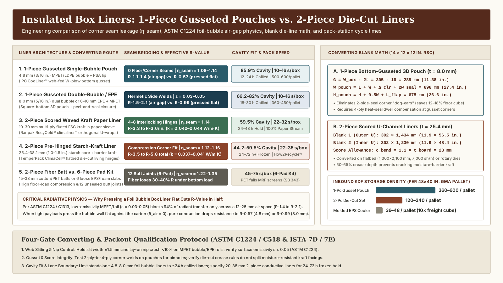
Selecting insulated box liners without matching converting geometry to wall thickness and air-gap physics causes severe corner seam air leakage (losing 28% to 35% of flat-slab R-value in unsealed 6-pad kits), crushed bottom insulation under heavy payloads, and thawed 48-hour shipments when a 4.8 mm foil bubble box liner is pressed flat against the corrugated wall (collapsing its thermal resistance from R-1.4 down to R-0.57). Specifying the right thermal box liner for shipping requires comparing web-fed 1-piece bottom-gusseted 3D pouches against flatbed or rotary 2-piece die-cut scored panel liners across seam bridging (η_seam), ASTM C1224 / C1313 radiative air-gap laws, die-line blank equations, and fulfillment pack-station cycle time.
Within our liner converting engineering guides, the insulated liner converting traveler maps the six inspection handoffs from incoming mother roll to cut blank, formed corner, joined seam, and carton installation, while our companion cold shipping boxes R-value and wall material comparison derives 3D box conduction shape factors (S_3D) and gel pack sweat control and sizing establishes internal phase-change refrigerant mass. This guide provides the structural converting, material physics, and blank-sizing specification comparing 1-piece collapsible gusseted pouches against 2-piece pre-hinged die-cut liners.
Compare 1-piece gusseted pouch liners and 2-piece die-cut thermal box liners
When converting flat web or sheeted stock into knock-down-flat (KDF) insulated box liners for Regular Slotted Cartons (RSCs), packaging engineers choose between three structural architectures documented across Insulated Products Corporation (IPC CooLiner™), TemperPack (ClimaCell®), Ranpak (RecyCold® climaliner™), and Sonoco ThermoSafe (ISC Labs™):
| Design & Operational Metric | 1-Piece Bottom-Gusseted 3D Pouch Liner | 2-Piece Die-Cut Scored / Pre-Hinged Liner | 6-Piece Flat Pad Kit (Legacy Reference) |
|---|---|---|---|
| Primary Liner Geometry & Converting Route | Web-fed 1-piece collapsible pouch with inward W-fold bottom gusset, 2 vertical side heat welds, and extended top closure lip (IPC CooLiner™, Bartelt pouch route) | Sheet-fed 2-piece rotary/flatbed die-cut blanks with scored living hinges (orthogonal U-channels or 4-wall sleeve + pads: ClimaCell®, RecyCold® climaliner™) | 6 individual guillotine/die-cut rectangular slabs (1 floor, 4 walls, 1 lid) assembled loosely inside the RSC (die-cut EPS, PUR, or foam pads) |
| Internal Seam Count & Air-Leakage Path | 0 floor or vertical corner seams; continuous welded barrier film blocks convective cold-air drainage (chimney bypass) |
4 to 8 overlapped/interlocking seams; pre-creased hinges seal 4 corners while carton compression closes interlocking edges |
12 unsealed straight butt joints (4 vertical + 8 horizontal); 1–3 mm tolerance gaps cause severe convective air leakage |
Seam Bridging Multiplier (η_seam) & Retained R_box |
η_seam = 1.08 – 1.14( retains 74%–78% of system R-value when PSA top lip is sealed) |
η_seam = 1.12 – 1.18( retains 70%–76% of flat-slab ASTM C518 R-value) |
η_seam = 1.22 – 1.35( retains only 65%–72% of flat-slab R-value) |
| Top Closure Mechanism | Peel-and-seal PSA adhesive strip (12–25 mm release liner on fold-over flap), double fold + tape, or impulse heat seal |
Scored top flaps fold inward 90° (or separate top pad drops in) and are held shut by outer RSC carton flap compression + tape |
Loose top plug/lid slab placed over payload; relies entirely on outer RSC top flaps to prevent lifting |
Usable Cavity Volume % (in 14 × 12 × 12 in. RSC) |
82% – 86% (tight fit, 4.8–8.0 mm wall)64% – 70% (with 12.7 mm radiant air gap) |
58% – 62% (at 1.0 in. / 25.4 mm wall)44% – 48% (at 1.5 in. / 38.1 mm wall) |
58% – 62% (at 1.0 in. / 25.4 mm wall)44% – 48% (at 1.5 in. / 38.1 mm wall) |
Manual Pack-Station Cycle Time (s/box) |
10 – 16 s / box (225–360 boxes/h)( 7–10 s/box on semi-auto pneumatic mandrel) |
22 – 35 s / box (103–164 boxes/h)(pre-breaking 4–6 scores + 2-part orthogonal insertion) |
45 – 75 s / box (48–80 boxes/h)(juggling 6 loose slabs per carton + orientation errors) |
KDF Pallet Density (48 × 40 in. GMA Pallet) |
360 – 600 liners / pallet( 4.8–8.0 mm collapsed pouches) |
120 – 240 sets / pallet( 19–38 mm flat-stacked blanks; 80% cube reduction vs. EPS) |
90 – 180 sets / pallet(vs. only 36–48/pallet for 1-piece molded EPS coolers) |
ISTA 7D / 7E Thermal Transit Boundary |
12 h – 24 h overnight chilled (+2 to +8 °C)(or secondary inner vapor/radiant liner inside a 2-piece box) |
24 h – 72 h+ chilled or frozen (≤ -18 °C)(high conductive wall thickness t = 20–38 mm) |
24 h – 72 h chilled or frozen(requires 15%–20% extra coolant vs. 2-piece hinged to offset leaks) |
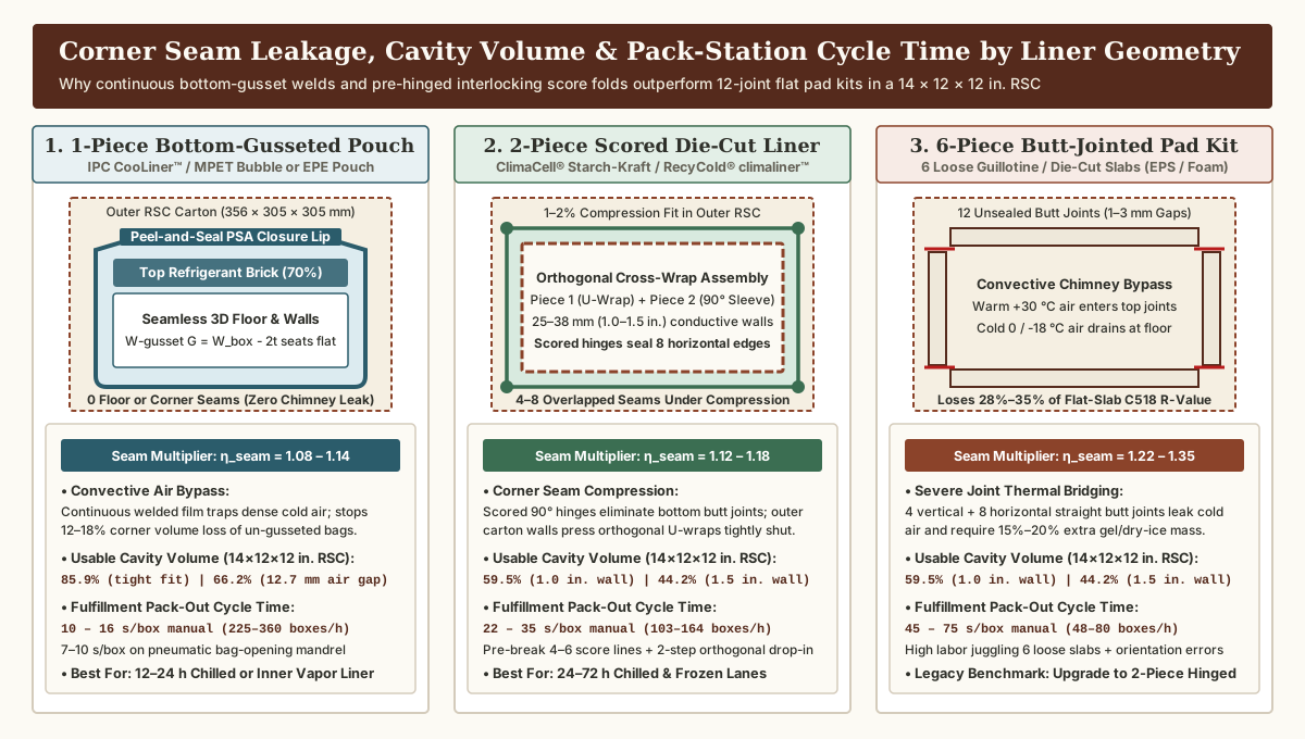
1. Corner seam air leakage and convective chimney bypass (η_seam)
As derived in our cold shipping boxes R-value and 3D shape-factor analysis, heat enters an assembled rectangular liner not only by planar conduction through its six faces, but also via 3D edge and corner geometric fanning (Langmuir shape factor S_3D) and convective air bypass through panel joints (seam bridging multiplier η_seam):
-
1-Piece Bottom-Gusseted / Square-Bottom 3D Pouch Liners (
IPC CooLiner™, MPET Foil Bubble & EPE Foam Pouches):- Zero Vertical Wall or Floor Seams: Formed from a continuous flexible web folded through an inward W-plow gusseter and heat-welded along two vertical side margins (
positioned outside the expanded square floor footprint, as detailed in Bartelt Packaging’s bottom-gusset pouch forming engineering), a 1-piece gusseted liner unfolds into a seamless rectangular floor and four continuous vertical walls. - Stopping Convective Chimney Drainage: When top-loaded gel packs or dry ice cool the internal air cavity to
0 °Cor-18 °C, that cold air is11% to 19%denser than+30 °Cambient air (ρ_0°C = 1.293 kg/m³vs.ρ_30°C = 1.164 kg/m³). In an unsealed multi-panel box, dense cold air drains out of the bottom floor seams by gravity while warm ambient air is sucked in through the top gaps—a buoyancy-driven convective chimney effect. Because a 1-piece bottom-gusseted pouch has a continuous welded basin and seals at the top via an extended fold-over flap with a12 to 25 mmpeel-and-seal acrylic pressure-sensitive adhesive (PSA) strip, it holdsη_seam = 1.08 to 1.14. - The Flat 2-Side-Seal “Dog-Ear” Trap vs. True Bottom-Gusset Geometry: If a buyer orders an ordinary flat 2-side-seal pillow pouch (
with no bottom gusset) and drops it into a rectangular carton, the bottom corners pinch into triangular “dog-ears” that waste12% to 18%of lower carton volume, bridge across the box corners, and place tensile tearing loads on the side welds when heavy payload cartons are loaded (see ourinsulated shipping boxes fit guide). Specifying a true bottom gusset with depthG = W_box - 2·t_linerallows the pouch floor to seat dead-flat across100%of the carton base.
- Zero Vertical Wall or Floor Seams: Formed from a continuous flexible web folded through an inward W-plow gusseter and heat-welded along two vertical side margins (
-
2-Piece Die-Cut Scored & Pre-Hinged Thermal Box Liners (
TemperPack ClimaCell®,Ranpak RecyCold® climaliner™, and Die-Cut Foam/Fiber Sets):- Orthogonal Interlocking U-Channel (
Cross-Wrap) vs. Sleeve-and-Pad Geometry: Thick conductive insulation boards (19 to 38 mm/0.75 to 1.5 in.starch-kraft foam, multi-ply waved kraft paper, or closed-cell PE foam) are too rigid to fold through a film plow gusseter. Instead, converters die-cut and crease two flat rectangular blanks that erect into an orthogonal interlocking enclosure:Blank 1folds along four90°score lines into a longitudinal U-channel covering the floor, two opposite end walls, and two top flaps;Blank 2slides insideBlank 1at a90°angle to cover the two remaining side walls while double-lining the floor and top ceiling (or forms a 4-wall continuous creased sleeve capped by top and bottom pads). - Living Hinges vs. 6-Piece Butt-Joint Leakage: An older 6-piece flat pad kit creates 12 unsealed straight butt joints (
4 vertical corners + 4 top edges + 4 bottom edges) with1 to 3 mmdimensional tolerance gaps (η_seam = 1.22 to 1.35, losing28% to 35%of flat-slabASTM C518R-value). A 2-piece pre-hinged die-cut liner replaces 4 to 8 of those open joints with continuous creased living hinges and uses a1% to 2%interference fit inside the outer corrugated RSC so the carton walls press the orthogonal edges tightly shut (η_seam = 1.12 to 1.18).
- Orthogonal Interlocking U-Channel (
2. Inner cavity volume utilization (V_cavity / V_carton) and fulfillment cycle time
For an outer RSC carton with interior dimensions L_box × W_box × H_box (interior volume V_carton = L_box × W_box × H_box), installed liner wall thickness t_eff, and corner fold/overlap allowance δ_fold, the usable internal payload and coolant cavity volume (V_cavity) and volumetric utilization ratio (η_vol) are:
V_cavity = (L_box - 2·t_eff - δ_fold) × (W_box - 2·t_eff - δ_fold) × (H_box - 2·t_eff - δ_fold)

η_vol    = V_cavity / V_carton
Evaluating a standard 14 × 12 × 12 in. (356 × 305 × 305 mm) outer RSC carton (V_carton = 2,016 in.³ = 33.04 L, parcel carrier dimensional weight = 15 lb at 139 in.³/lb):
- 1-Piece Gusseted Single-Bubble
Foil Bubble Box Liner(t = 3/16 in. / 4.8 mm, tight contact fit,δ_fold = 0.25 in.): Internal cavity= 13.38 × 11.38 × 11.38 in. = 1,732 in.³(28.39 L) →85.9%cavity volume utilization (consumes only 14.1% of box volume, but direct wall contact sacrifices radiant R-value). - 1-Piece Gusseted Double-Bubble
Foil Bubble Box Liner(t = 5/16 in. / 8.0 mmwall +0.5 in. / 12.7 mmcorrugated stand-off air gap): Internal cavity= 12.38 × 10.38 × 10.38 in. = 1,334 in.³(21.86 L) →66.2%cavity volume utilization (unlocks full ASTM C1224 low-emissivity radiant resistance of R-1.5 to R-2.1). - 2-Piece Die-Cut
1.0 in.(25.4 mm) Starch-Kraft / Waved Paper Liner (ClimaCell®orRecyCold®double-wall): Internal cavity= 12.0 × 10.0 × 10.0 in. = 1,200 in.³(19.66 L) →59.5%cavity volume utilization (insulation walls occupy 40.5% of outer carton volume). - 2-Piece Die-Cut
1.5 in.(38.1 mm) Heavy Frozen Liner (ClimaCell®orEPS): Internal cavity= 11.0 × 9.0 × 9.0 in. = 891 in.³(14.60 L) →44.2%cavity volume utilization (insulation occupies 55.8% of the 14 × 12 × 12 in. carton—requiring stepping up to a 15 × 13 × 13 in. outer carton to preserve a 19.7 L payload cavity).
At high-velocity meal-kit, perishable food, and specialty pharmacy fulfillment stations, pack-out cycle time (seconds per box) directly governs labor cost per shipment:
- 1-Piece Gusseted Pouch Liner:
10 to 16 seconds/boxmanual (pick flat pouch, snap open mouth, drop into carton, load payload and gel packs, peel PSA release strip, press top lip shut:225 to 360 boxes/hour per operator), or7 to 10 seconds/boxon a semi-automated pneumatic bag-opening mandrel. - 2-Piece Pre-Hinged Scored Die-Cut Liner:
22 to 35 seconds/boxmanual (pre-break 4 to 6 score lines to 90°, seat Piece 1 U-channel, slide Piece 2 orthogonally inside Piece 1, load payload, fold inner flaps:103 to 164 boxes/hour per operator). - 6-Piece Flat Butt-Jointed Pad Kit:
45 to 75 seconds/boxmanual (orient and insert 1 floor pad, 2 long side pads, and 2 short end pads while holding loose slabs upright, load payload, place lid pad:48 to 80 boxes/hour per operator).
Key Takeaway: Specify a 1-piece bottom-gusseted pouch liner (
η_seam = 1.08–1.14,10–16 s/box,66%–86%usable cavity volume) for high-speed12 to 24 hovernight chilled fulfillment, and specify a 2-piece pre-hinged die-cut liner (η_seam = 1.12–1.18,22–35 s/box,25–38 mmconductive wall) whenever24 to 72 hsummer chilled or strictly frozen (≤ -18 °C) lanes requireR-3.3 to R-5.8wall resistance.
Evaluate foil bubble box liner emissivity against conductive foam, fiber, and paper liners
A frequent cause of summer thermal qualification failures in e-commerce cold chains is treating a 4.8 mm (3/16 in.) or 8.0 mm (5/16 in.) foil bubble box liner as a direct thermal substitute for a 25.4 to 38.1 mm (1.0 to 1.5 in.) conductive thermal box liner for shipping.
1. ASTM C1224 / C1313 low-emissivity air-gap physics vs. the conductive contact penalty
As established by Metal Architecture, Fi-Foil Company, and the National Insulation Association (NIA) under ASTM C1224 (Standard Specification for Reflective Insulation for Building Applications) and ASTM C1313 (Standard Specification for Sheet Radiant Barriers), commercial foil bubble box liner webs combine two heat-transfer mechanisms:
- Low-Emissivity Outer Facings (
MPETvs. Pure Aluminum Foil):- Vacuum-Metallized Polyester (
MPET,12 µmBOPET film vapor-deposited with99.5%pure aluminum to optical densityOD 2.2 to 2.8): Exhibits surface infrared emissivityε = 0.04 to 0.06(94% to 96%thermal radiant reflectivity). - Pure Rolled Aluminum Foil (
7 to 9 µmfoil laminated to LDPE tie layers): Exhibits surface infrared emissivityε = 0.03 to 0.04(96% to 97%radiant reflectivity). Both substrates easily satisfy theASTM C1224 / C1313specification threshold of emittanceε ≤ 0.10(reflectivity ≥ 90%).
- Vacuum-Metallized Polyester (
- Cellular Polyethylene Bubble Core (
Single-Bubblevs.Double-Bubble):- Single-Bubble (
3/16 in. / 4.8 mmnominal caliper,10 mmbubble diameter,180 to 240 g/m²basis weight): One layer of trapped dry-air LDPE/LLDPE bubbles laminated between two reflective facings (MPET/Bubble/MPET) or one reflective outer face and one food-contact white LDPE inner face (MPET/Bubble/White-PE). - Double-Bubble (
5/16 in. / 8.0 mmnominal caliper,280 to 380 g/m²basis weight): Two stacked layers of LDPE air cells (MPET/Bubble/Bubble/MPET), increasing core thickness by67%and resisting point-load pinch-through under frozen carton corners.
- Single-Bubble (
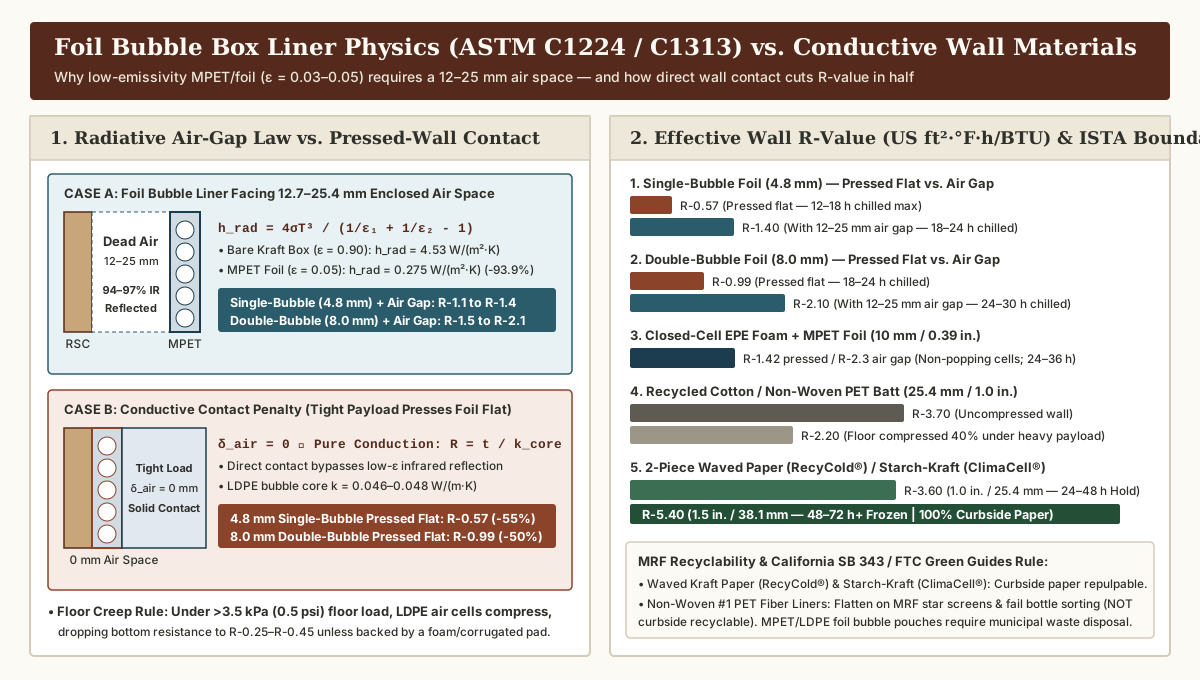
Across an enclosed planar air space of thickness δ_air (12.7 to 25.4 mm / 0.5 to 1.0 in.) bounded by two parallel surfaces at mean absolute temperature T_mean ≈ 290 K (17 °C) with surface emissivities ε_1 and ε_2, linearized radiative heat-transfer conductance (h_rad) follows the Stefan-Boltzmann law (σ = 5.670 × 10⁻⁸ W/(m²·K⁴)):
h_rad [W/(m²·K)] = (4 × σ × T_mean³) / [ (1 / ε_1) + (1 / ε_2) - 1 ]Compare how h_rad and total wall resistance behave across three installation states inside an outer corrugated RSC (where kraft paper emissivity ε_kraft = 0.90):
- State 1 — Unlined Kraft Corrugated Air Gap (
ε_1 = 0.90,ε_2 = 0.90):h_rad,kraft = [ 4 × (5.670 × 10⁻⁸) × (290)³ ] ÷ [ (1 / 0.90) + (1 / 0.90) - 1 ] = 5.531 ÷ 1.222 = 4.53 W/(m²·K). In an unlined air space, infrared radiation accounts for~75%of total heat transfer across the gap. - State 2 —
Foil Bubble Box LinerFacing a12.7–25.4 mm(0.5–1.0 in.) Enclosed Dead Air Space (ε_1 = 0.05,ε_2 = 0.90):h_rad,foil = 5.531 ÷ [ (1 / 0.05) + (1 / 0.90) - 1 ] = 5.531 ÷ 20.111 = 0.275 W/(m²·K). The low-emissivity MPET/foil surface slashes radiative heat transfer across the air space by93.9%, combining with the trapped air gap and bubble core to deliverR-1.1 to R-1.4(0.19 to 0.25 m²·K/W) for4.8 mmsingle-bubble andR-1.5 to R-2.1(0.26 to 0.37 m²·K/W) for8.0 mmdouble-bubble. - State 3 — The Conductive Contact Penalty (
Zero Air Gap, δ_air = 0 mm): When a packer stuffs a foil bubble box liner tightly with heavy food containers and frozen gel bricks so the outer MPET face is pressed flat against the inner corrugated box wall (δ_air = 0), there is no optical air space across which infrared radiation can occur. Heat transfers purely by solid-and-gas conduction (R = t / k_core) through the thin4.8 mmor8.0 mmpolyethylene bubble layer (k_core ≈ 0.046 to 0.048 W/(m·K)):
R_contact,single-bubble (4.8 mm) = 0.0048 m ÷ 0.048 W/(m·K) = 0.100 m²·K/W = R-0.57 (US ft²·°F·h/BTU)

R_contact,double-bubble (8.0 mm) = 0.0080 m ÷ 0.046 W/(m·K) = 0.174 m²·K/W = R-0.99 (US ft²·°F·h/BTU)
Pressing a foil bubble box liner flat against the carton wall cuts its effective thermal resistance in half (from R-1.4 down to R-0.57 for single-bubble, and down to R-0.25–R-0.40 under the bottom floor where payload weight > 3.5 kPa / 0.5 psi creeps and flattens LDPE air cells).
2. Five commercial box liner material families compared (ASTM C518, ISTA 7D/7E, and MRF recycling)
To select the right substrate for temperature-controlled packaging types and protective mailers and boxes, compare the five commercial liner material families across conductive core k-value, air-gap vs. pressed R-value, floor compression under load, ISTA 7D / 7E transit hold, and municipal Materials Recovery Facility (MRF) sorting behavior:
| Material Construction & Commercial Examples | Nominal Thickness (t) & Core Conductivity (k) |
Effective Wall R-Value (Air Gap vs. Pressed Flat) |
Floor Load Compression & Moisture Barrier Behavior | ISTA 7D / 7E Transit Boundary & MRF End-of-Life Pathway |
|---|---|---|---|---|
1. Single-Bubble Foil Bubble Box Liner (3/16 in.)MPET (12 µm) or Al Foil (7 µm) + single LDPE bubble core + MPET or white PE inner face(IPC CooLiner™ single-bubble gusseted pouch) |
4.8 mm (0.188 in.)k_core = 0.048–0.052 W/(m·K)Surface ε = 0.03–0.06 |
• With 12–25 mm air gap: R-1.1 to R-1.4 (0.19–0.25 m²·K/W)• Pressed flat ( 0 mm gap): R-0.55 to R-0.65 (0.10–0.11 m²·K/W) |
Waterproof vapor barrier stops gel sweat; however, bottom loads > 3.5 kPa (0.5 psi) creep and flatten LDPE bubbles over 24–48 h |
12 h – 24 h overnight chilled (+2 to +8 °C);Multi-material MPET/LDPE laminate is not curbside recyclable (municipal solid waste) |
2. Double-Bubble Foil Bubble Box Liner (5/16 in.)MPET / Dual-LDPE Bubble / MPET (280–380 gsm)(Heavy-duty reflective 3D gusseted box pouches) |
8.0 mm (0.313 in.)k_core = 0.045–0.048 W/(m·K)Surface ε = 0.03–0.05 |
• With 12–25 mm air gap: R-1.5 to R-2.1 (0.26–0.37 m²·K/W)• Pressed flat ( 0 mm gap): R-0.90 to R-1.10 (0.16–0.19 m²·K/W) |
Dual bubble layer resists point-load pinch-through better than single bubble; hermetic vapor & condensate barrier | 18 h – 30 h chilled (or inner radiant pouch inside a rigid box for 48–72 h frozen); not curbside recyclable |
3. Closed-Cell EPE Foam + Foil Laminate (3 – 10 mm)Extruded closed-cell polyethylene foam ( 20–28 kg/m³) + MPET film(1-piece gusseted pouches or 2-piece die-cut foam liners) |
3.0 – 10.0 mm (0.12–0.39 in.)k_core = 0.038–0.042 W/(m·K)Surface ε = 0.04–0.06 |
• With 12–25 mm air gap (6 mm EPE): R-1.5 to R-1.9• Pressed flat ( 6 mm / 10 mm EPE): R-0.85 / R-1.42 |
Fine micro-cellular EPE foam will not pop under sharp frozen carton corners and retains > 88% thickness under 5 kPa floor load |
18 h – 36 h chilled (or 24–48 h in 10–15 mm die-cut EPE); MPET/EPE laminate requires industrial scrap recovery |
4. Recycled Cotton/Denim & Non-Woven PET Fiber BattsCarded shoddy cotton, scoured wool, or #1 PET fiber batt enclosed in PE or perforated film(2-piece wrapped fiber liners evaluated by ThermoSafe ISC Labs) |
15.0 – 38.1 mm (0.6–1.5 in.)k_core = 0.036–0.041 W/(m·K)( R-3.5 to R-4.0/in. unloaded) |
• Uncompressed (1.0 in. / 1.5 in.): R-3.7 / R-5.6• Compressed 40% under floor load: drops to R-2.2 / R-3.3 |
Soft fibrous batts cushion glass jars well, but compress 30%–50% under heavy floor loads and wick gel sweat if the PE barrier tears |
24 h – 48 h chilled / frozen;Non-woven #1 PET liners fail MRF bottle sorting (wrap on star screens, violating CA SB 343) |
| 5. Curbside-Recyclable Waved Kraft & Starch-Kraft Liners Multi-ply waved FSC kraft paper (Ranpak RecyCold® climaliner™) or bio-starch foam + kraft (TemperPack ClimaCell®) |
10.0 – 38.1 mm (0.4–1.5 in.)k_core = 0.037–0.044 W/(m·K)( R-3.2 to R-3.9/in.) |
• 1.0 in. (25.4 mm) wall: R-3.3 to R-3.9 (0.58–0.69 m²·K/W)• 1.5 in. (38.1 mm) wall: R-4.8 to R-5.8 (0.85–1.02 m²·K/W) |
Semi-rigid starch-kraft (ClimaCell®) and multi-wall fluted kraft (RecyCold®) resist floor crushing; pair with non-woven or paper gel packs |
24 h – 72 h+ chilled & frozen (≤ -18 °C) under ISTA 7D / 7E; 100% curbside paper recyclable (How2Recycle®) |
As Sonoco ThermoSafe’s ISC Labs™ engineering evaluation of non-woven PET liners versus molded EPS and cellulose shippers documents, packaging engineers must avoid two common pitfalls with flexible fibrous liners:
- Floor Load Compression Loss: Under the weight of frozen food cartons and phase-change gel bricks, soft non-woven PET or cotton shoddy floor pads compress by
30% to 50%, losing nearly half of their bottom conductive resistance right where dense0 °Cor-18 °Cair pools. - Municipal MRF Star-Screen Wrapping (
California SB 343&FTC Green Guides): Although non-woven polyester fiber mats share the#1 PETresin code of rigid beverage bottles, municipal Materials Recovery Facilities (MRFs) separate2Dflat flexible materials from3Drigid containers across inclined rotating disc/star screens. Flexible#1 PETfiber liners behave like2Dsheet/film, wrapping around MRF star-screen axles or diverting into the paper stream as a contaminant rather than reaching the optical PET bottle sorter—failing the60%municipal access threshold required for unqualified recyclability claims under CaliforniaSB 343and theFTC Green Guides. By contrast, all-paper fluted liners (Ranpak RecyCold® climaliner™) andHow2Recycle®-certified starch-kraft liners (TemperPack ClimaCell®) repulp directly alongside the outer corrugated RSC.
Key Takeaway: Never equate a
4.8–8.0 mmfoil bubble box liner pressed flat against a carton wall (R-0.57 to R-0.99) with a25–38 mmconductive thermal box liner for shipping (R-3.3 to R-5.8). To unlock a foil bubble liner’sR-1.4 to R-2.1radiant rating underASTM C1224, maintain a12 to 25 mmenclosed air gap (or use it as an inner radiant/vapor pouch inside a 2-piece corrugated or paper-lined box).
Size converting blanks for gusseted pouches vs. rotary and flatbed die-cut sheets
Connecting our carton interior dimension worksheet with upstream slitting and rewinding and insulated liner converting handoffs requires two distinct blank-sizing derivations depending on whether the liner is formed on a web-fed bottom-gusset pouch machine (Bartelt / pouch-making route) or a flatbed/rotary steel-rule die-cutter (Koenig & Bauer CutPRO Q 2.1 route).
1. Geometric blank equations for a 1-piece bottom-gusseted 3D pouch liner
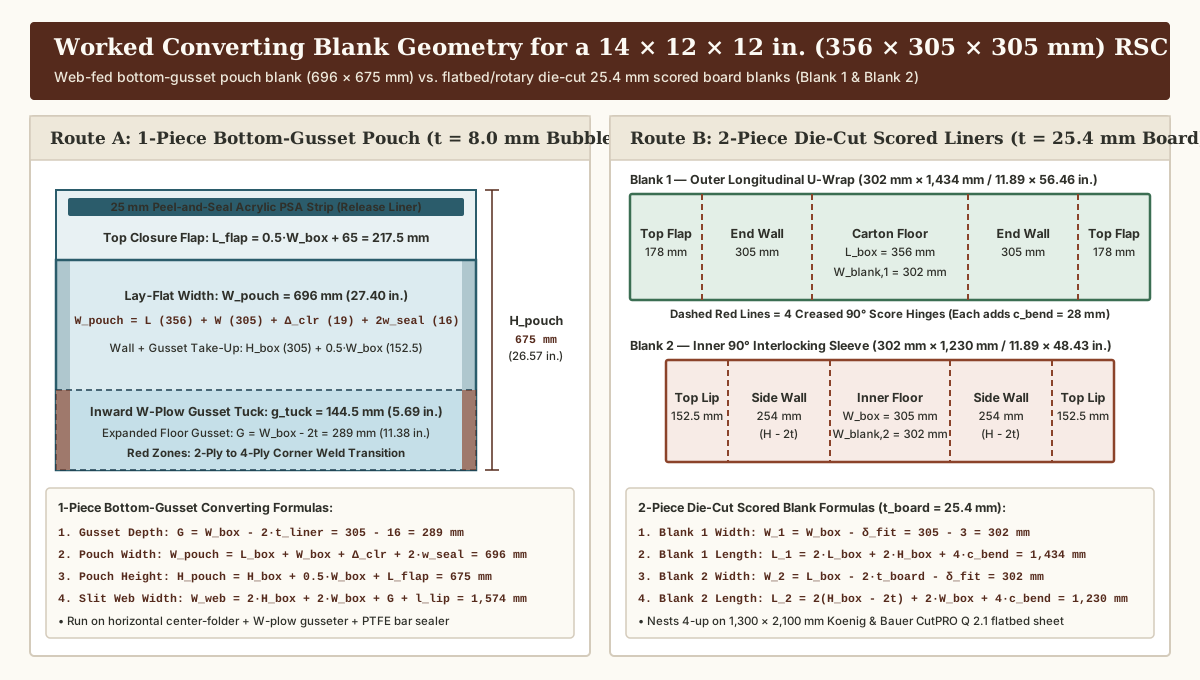
Given an erected outer RSC carton with measured inside dimensions L_box × W_box × H_box and a flexible reflective bubble or EPE foam web of thickness t_liner (4.8 mm single-bubble or 8.0 mm double-bubble):
- Bottom Gusset Expanded Span (
G) and Inward W-Plow Tuck Depth (g_tuck): For the pouch floor to open into a flatL_box × W_boxrectangle without corner dog-earing, the total expanded bottom gusset spanGmust equal the interior carton width minus two liner wall thicknesses:
G      = W_box - 2·t_liner

g_tuck = G / 2 = (W_box / 2) - t_liner
Here g_tuck is the inward fold depth creased by the W-plow gusseter between the front and back pouch panels, creating a 4-ply laminate stack along the lower g_tuck section of both vertical side welds.
- Lay-Flat Pouch Width (
W_pouch): Before opening, the internal lay-flat pouch perimeter (2 × W_pouch,int) must wrap all four interior walls of the carton (2·L_box + 2·W_box) plus a perimeter insertion and corner-turn clearance allowanceΔ_clearance = 12 to 25 mm(0.5 to 1.0 in.) so operators can slide the pouch smoothly into the RSC without tearing the side welds, plus two side heat-seal margins2·w_seal(typically w_seal = 6 to 10 mm/0.25 to 0.375 in.each):
W_pouch = L_box + W_box + Δ_clearance + 2·w_seal- Lay-Flat Pouch Height (
H_pouch) and Slit Mother-Roll Web Width (W_web): When a flat bottom-gusseted pouch expands into a 3D box, transitioning the flat front and back walls around the bottom gusset consumes a vertical take-up equal to half the box width (0.5·W_box). Adding the interior box heightH_boxand the top fold-over closure flapL_flap(spanning half the box width plus a 50 to 75 mm / 2 to 3 in. peel-and-seal overlap lip l_seal_lip:L_flap = 0.5·W_box + l_seal_lip) yields:
H_pouch = H_box + 0.5·W_box + L_flap = H_box + W_box + l_seal_lip

W_web   = 2·H_box + 2·W_box + G + l_seal_lip
Where W_web is the required slit mother-roll web width (specified on the slitting and rewinding input sheet) when running on a horizontal center-folder + W-plow bottom-gusset bag-making line.
2. Geometric blank equations for a 2-piece die-cut scored thermal box liner
For semi-rigid or multi-ply conductive boards of caliper t_board (e.g., 25.4 mm / 1.0 in. or 38.1 mm / 1.5 in. TemperPack ClimaCell®, Ranpak RecyCold® climaliner™, or die-cut EPE foam) converted on a flatbed platen die-cutter (such as the Koenig & Bauer CutPRO Q 2.1 running 1,300 × 2,100 mm / 51.2 × 82.7 in. sheets at up to 7,000 sheets/hour) or a wide-web rotary die-cutter (8,000 to 12,000 sheets/hour), each 90° inside score/crease requires a hinge bend allowance c_bend ≈ 1.0·t_board to 1.4·t_board to compensate for inner face compression at the fold:
Blank 1 (Outer Longitudinal U-Channel — Floor + 2 End Walls + 2 Top Flaps):
  W_blank,1 = W_box - δ_fit
  L_blank,1 = 2·L_box + 2·H_box + 4·c_bend

Blank 2 (Inner 90° Interlocking Sleeve — 2 Side Walls + Inner Floor & Ceiling):
  W_blank,2 = L_box - 2·t_board - δ_fit
  L_blank,2 = 2·(H_box - 2·t_board) + 2·W_box + 4·c_bend
3. Side-by-side worked example (14 × 12 × 12 in. / 356 × 305 × 305 mm RSC carton)
Compare the exact production blank dimensions required to line the same 14 × 12 × 12 in. (356 × 305 × 305 mm) RSC carton via Route A (8.0 mm double-bubble gusseted pouch) versus Route B (25.4 mm / 1.0 in. 2-piece die-cut scored liner):
-
Route A — 1-Piece Bottom-Gusseted
Foil Bubble Box Liner(t_liner = 8.0 mm,Δ_clearance = 19 mm,w_seal = 8 mm,l_seal_lip = 65 mm):- Bottom Gusset Span (
G) & Plow Tuck (g_tuck):G = 305 mm - 2 × (8.0 mm) = 289 mm(11.38 in.) →g_tuck = 144.5 mm(5.69 in.inward fold). - Lay-Flat Pouch Width (
W_pouch, machine-direction cut pitch):W_pouch = 356 + 305 + 19 + 2 × (8) =696 mm(27.40 in.). - Top Flap (
L_flap) & Lay-Flat Pouch Height (H_pouch):L_flap = (305 ÷ 2) + 65 = 217.5 mm(8.56 in.) →H_pouch = 305 + 152.5 + 217.5 =675 mm(26.57 in.). - Slit Mother-Roll Web Width (
W_web):W_web = 2 × (305) + 2 × (305) + 289 + 65 =1,574 mm(61.97 in.).
- Bottom Gusset Span (
-
Route B — 2-Piece Die-Cut Scored
1.0 in.(25.4 mm) Liner (c_bend = 28 mm,δ_fit = 3 mm):- Blank 1 (Outer Longitudinal U-Wrap + Top Flaps):
W_blank,1 = 305 - 3 =302 mm(11.89 in.);L_blank,1 = 2 × (356) + 2 × (305) + 4 × (28) =1,434 mm(56.46 in.), scored at178 mm,511 mm,895 mm, and1,228 mm(nests 4-up per 1,300 × 2,100 mm Koenig & Bauer CutPRO Q 2.1 flatbed sheet). - Blank 2 (Inner Transverse Interlocking Sleeve):
W_blank,2 = 356 - 2 × (25.4) - 3 =302 mm(11.89 in.);L_blank,2 = 2 × (305 - 50.8) + 2 × (305) + 4 × (28) =1,230 mm(48.43 in.).
- Blank 1 (Outer Longitudinal U-Wrap + Top Flaps):
4. Inbound KDF warehouse pallet density (48 × 40 in. GMA pallet at 60 in. stack height)
Because both liner routes ship and store knock-down-flat (KDF), they dramatically reduce inbound freight and warehouse rack footprint compared to pre-molded rigid EPS foam chests:
- 1-Piece Collapsed Gusseted Pouches (
4.8 to 8.0 mmwall,9.6 to 16 mmfolded pouch caliper):360 to 600 liners per GMA pallet(10× to 15×the storage density of molded EPS coolers). - 2-Piece Die-Cut Scored Blanks (
25.4 to 38.1 mmwall,51 to 76 mmstacked pair height):120 to 240 complete 2-piece sets per GMA pallet(reducing inbound truckload and pallet cube by up to 80% versus molded EPS, as documented forTemperPack ClimaCell®). - 1-Piece Molded Rigid EPS Foam Coolers (
14 × 12 × 12 in.exterior): Only36 to 48 coolers per GMA pallet(shipping ~85% empty air).
Key Takeaway: Always specify a true bottom gusset (
G = W_box - 2·t_liner) on 1-piece pouch liners to prevent12%–18%corner dog-ear volume loss, and includec_bend = 1.0–1.4 × t_boardper90°crease on 2-piece die-cut blanks so the inner interlocking sleeve seats without buckling or leaving corner gaps.
Verify converting handoffs and ISTA 7D/7E packout boundaries before production release
Before releasing a new insulated box liner specification to production, execute this four-gate quality verification across the slitting, bag sealing, liner converting, and thermal chamber qualification stages (grounded in CAMPEN Machinery, Calemard, Audion Elektro, and ThermoSafe ISC Labs ISTA 7D / 7E protocols):
| Converting & Packout Gate | Engineering Parameter to Record | Mandatory Acceptance Threshold & Stop Rule |
|---|---|---|
Gate 1: Mother-Roll Slitting & Nip Compression Check (Web-Fed Pouch Route) |
Record slit roll width (W_web ± 1.5 mm), MPET/foil thickness (12 µm MPET vs. 7 µm Al foil), surface emissivity (ε ≤ 0.05 per ASTM C1224 / C1313), and unloaded bubble or EPE foam caliper (4.8 mm vs. 8.0 mm, per slitting input sheet). |
Stop Rule: Reject any slit mother roll showing > 10% caliper loss from excessive rewind lay-on roller nip pressure or foil edge delamination along the slit boundary. |
Gate 2: Bottom-Gusset 4-Ply Corner Weld & PSA Lip Trial (Pouch Route) |
Verify bottom-gusset tuck symmetry (g_tuck = G / 2 ± 2.0 mm) and heat-seal bar temperature, PTFE barrier cloth condition, and dwell pressure across the 2-ply-to-4-ply gusset transition zone (per bag sealer trial guide). Test PSA strip peel tack at +2 °C. |
Stop Rule: Reject pouches exhibiting unsealed pinhole channels at the 4-ply gusset transition edge or thermal burn-through/shrinkage of the outer MPET film onto the sealing jaws. |
Gate 3: Die-Line Score Depth & Interlocking Fit Check (2-Piece Die-Cut Route) |
Record flatbed/rotary die-cut blank dimensions (± 1.5 mm), creasing rule penetration (50%–65% of board caliper), hinge bend allowance (c_bend), and loaded bottom-pad deflection under full payload + gel pack weight (per liner converting traveler). |
Stop Rule: Stop production if steel creasing rules crack the moisture-resistant kraft facing (exposing starch or fluted paper cores to condensate) or if erected 2-piece corners leave > 1.5 mm air gaps inside the RSC. |
Gate 4: ISTA 7D / 7E 24–48 h Chamber Qualification & MRF Labeling |
Qualify complete assembled packout in triplicate under ISTA 7D or ISTA 7E summer profiles at minimum and maximum payload. Record whether a foil bubble box liner maintains a 12–25 mm air gap or is pressed flat, and audit recycling claims (How2Recycle® vs. CA SB 343). |
Stop Rule: Never deploy a standalone 4.8–8.0 mm foil bubble box liner for 48 h summer frozen or chilled lanes without a conductive wall (or chamber proof), and never print curbside recycling claims on MPET/PE pouches or non-woven #1 PET fiber mats. |
Key Takeaway: Audit the converting line and the packed shipping carton as one coupled system: prevent cell crush during mother-roll slitting (
< 10%caliper loss), inspect the 2-ply-to-4-ply gusset weld or die-cut score hinge before loading, and qualify every24 hvs.48 hlane in anISTA 7Dor7Echamber with actual payload and refrigerant mass.
Technical basis and scope
Structural box liner specifications, radiative and conductive material properties, and converting equipment parameters in this guide are grounded in published technical documentation and industry standards from Metal Architecture / Fi-Foil Company and the National Insulation Association (ASTM C1224, ASTM C1313, and ASTM C518 reflective bubble laminate physics), Insulated Products Corporation (IPC CooLiner™ 1-piece collapsible gusseted box liners), Bartelt Packaging / ProMach (bottom-gusset HFFS 3D pouch forming geometry), TemperPack Technologies (ClimaCell® and WaveKraft™ pre-hinged starch-kraft thermal liners), Packaging Europe / Ranpak (RecyCold® climaliner™ two-piece fluted paper box liners), Sonoco ThermoSafe® ISC Labs™ (non-woven PET fiber liners vs. molded EPS/EOS™ and ISTA 7D / 7E qualification profiles), Packaging Europe / Koenig & Bauer (CutPRO Q 2.1 flatbed and rotary die-cutting systems for corrugated and insulating boards), and CAMPEN Machinery A/S, Calemard, and Audion Elektro (non-woven and laminated web slitting, winding tension, and multi-ply heat sealing). Geometric blank sizing equations, usable cavity volume ratios, fulfillment station cycle-time ranges, and GMA pallet density comparisons represent engineering planning models governed by carton dimensions, material caliper, and line tooling; always verify die lines and thermal hold times on assembled production samples (see our editorial policy).